20. Body and Interior

Body and Interior
This section contains special information on
cooling that is not found in the Service or the Bentley manuals.
All information contained in this FAQ
is provided by BMW enthusiasts who are not typically fully trained
in the art of BMW maintenance. As such, all information in this
FAQ is provided "as-is". Any use of this information
is strictly the responsibility of the using party. The supplier
of the information and the Webmeister assume no liability for
incorrect information or use of this information.
Index
One Touch Power
Window Module
Headrest Fix
Sound System Upgrade,
Subwoofer Installation
Removal of 6
series Instrument Panel
E24 Sunroof
Drain Clean Out
Clothes Rod
Archival Leather
Restoration (long)
Antenna Removal
Tips
Upper Center
Vent Removal
Rear Seats' Maintenance
Sport Seat Back
Removal
Leather Seat
Treatment
Rejuvenate those
front seats!!
Antennas - Power,
Rebuildable
Sport Seat
Disassembly/Reassembly
Permanent Garage
Door Opener
A/C Vent Friction
Window Tint Removal
Window Alignment
- Adjusting
Dome Light
Over Center Console Area
Lighted Rear View Mirror Install
Interior Door
Panel/Trim Removal
Speedometer
Repair
Front Seat Swap
Un-clogging
Sun Roof Drains
Door interchange
information--pre and post 82 U.S. models
Plastic Door
Clip Replacement
Power Door Mirror
Connector and Mirror Assembly/Mount Removal
Instrument and
Dash Panel Bulb Replacement
Door lock mechanisms
Power Seat Stuck All The Way Back
Trunk Lid Springs
Adding a New Interior Light
Sunroof and Headliner Panel Removal
Sun Shade Removal and Repair
Fresh Air Vents
One Touch
Power Window Module by Klaus Bertram
I would like to update the article on the One Touch Power Window Module by John N Zoas.
As I was interested in installing the mentioned kit into my '81 633CSi I tried chasing down one of the mentioned modules without any luck, the link does not work, the domain is no longer registered.
After a Google search I found a very similar module on the Autolöc website, it is called WC1000 - One Touch Up And Down Window Unit and lists for $39.95.
http://www.autoloc.com/detail.lasso?itemid=WC1000
I ordered one from Top End Motorsports for $35 including shipping, the installation was very simple and easy. It took less then 15 minutes to mount the unit under the shifter console and cut two wires, install a ground wire and run an extra 15 Amp power feed from the fuse box (very important, otherwise the unit will work intermittently).
Headrest
Fix - by Norm Grills
If your headrests fail to move
up and down but you can hear the motor turning, there is a potential
fix which is very simple. The way the motor is located in the
seat back, the cable hangs more or less vertically. It appears
that the cable "shrinks" and when it does it follows
gravity and settles in to the motor end and coming out of the
headrest drive. The easy fix for this is:
1) Remove the seat back by taking
two screws out of the bottom corners of the seat back UNDER the
seat back.
2) Slide the seat back down to
disengage the two clips at the top and remove the seat back. The
motor is now exposed.
3) Remove the motor from it's
bracket allowing removal of the cable from the motor.
4) Cut a piece of coathanger wire
1/4 - 3/8" long and drop it into the motor sqare hole drive.
Make sure there is enough of a gap between the end of the wire
and the top of the square drive for the cable to make a good engagement
with the motor. Shorten the wire if necessary.
5) Spin the cable, pushing it
upward to engage the headrest drive, making sure enough sticks
out the bottom end to engage the motor drive.
6) Re-assemble the motor into
the seat back and test for correct operation.
7) Re-install the seat back in
reverse order and proceed to do the other one.
8) Volunteer to help a friend
whose headrests are malfunctioning and be a hero!
Sound
System Upgrade, Subwoofer Installation - Justin Seiferth
If you want to improve the bass
in your coupe, a subwoofer is your best bet. Unfortunately, the
rear package shelf of our cars doesn't offer a good mounting location.
Fortunately, there is an alternative- you can locate free air
drivers behind the center fold-down arm using the trunk as an
infinite baffle. Make sure your driver is designed for "infinite
baffle" or "free-air" use. Here's a brief run down
of the procedure, if you want more details on any of the steps,
please e-mail.
Remove the rear seat- the whole
thing including the center console. Then using the center console
as a guideline make a hole for your speaker directly behind the
"flat" part of the console. You can cut the rear bulkhead
with a good quality soft metal jigsaw blade. Use a drill to start
the hole. Make SURE it's large enough to fully expose the driver.
Don't worry about the screw holes, you won't be mounting directly
to the bulkhead.
Use a piece of 1/2" or 3/4"
MDF or fiber board as your speaker mount. Cut a piece big enough
to hold your speaker, amp, crossover and other components you
may want mounted in the boot. My mount covers most of the bulkhead
in the trunk. You'll have to remove the trunk carpet section covering
this area and either cut a hole in it for the speaker or replace
it with a similar piece of carpet to keep your OEM stuff in case
you want to sell the car without this modification.
Mount the speaker on the side
of the board which will face the car inside the trunk. This will
entail cutting a hole in the MDF- don't worry it's easier than
the bulkhead to cut. Use all the speaker mount holes for a secure
fit and make sure not to warp the driver.
Wire up the speaker and amps and
get ready to install in your car. Get some small plastic spacers
at a home supply place and some 2" machine screws, bolts
and washers. Use at least 6 to mount the assembly. There are a
couple of convenient places on the bulkhead to drill. Before you
mount the assembly, wrap a 1/2" piece of foam rubber hose
about the hole through which the driver will fire. This is important
as it seals the assembly. Snug the assembly so this foam is mostly
crushed and the speaker is firmly mounted to the bulkhead. You'll
need a helper as the assembly will be heavy. This is the most
difficult task of the job.
Now the final step, cut a square
hole in the "flat" section of the center console behind
the flip down arm. Leave about 1/4" of plastic around the
left and right sides. There's enough space here to fully expose
an 8" driver. If you use something larger, don't worry it
will still sound great but an 8" driver will give plenty
of bass. You cover this hole with the drilled aluminum plate and
acoustic cloth an auto sound place will carry. You can get the
cloth to match any interior. Screw the plate over the hole and
cover the bolts with interior cover plastic bolt covers. If you
want an auto sound place to do this step, it should run about
$50 and blend in so well nobody will notice the cover unless you
point it out to them. My cover overlays the whole flat area in
the console.
Now put everything back together.
The whole process should take about three hours including running
the wiring for the amps and speakers back to the boot. DON'T use
the OEM wiring for the deck speakers- the wire is garbage. DO
use a nice fat amp supply line straight from the battery(don't
forget to fuse!). If you cross the system over at about 50 -100Hz
and give it around a 100w amp (for the subwoofer) you'll have
a beautifully sounding system. I found an electronic crossover
another worthwhile investment. You can also cover the interior
side of the rear bulkhead with "dynamat" or equivalent
to greatly reduce the interior sound level of your car.
Removal
of 6 series Instrument Panel
- "Gene M."
This procedure is expanded from
Chilton's, which I followed on my 83 633csi to replace the NiCads.
The surprise was that there were no surprises.
1. Disconnect the battery ground
cable and remove steering wheel.
2. Lift the glass cover off the
check control (left side of instrument cluster) by gently prying.
Remove 3 mounting screws underneath and pull out the check control
housing and remove plug in the back.
3. Remove the fog lamp switch
from the dash (you can leave the wires connected).
4. To the right of the fog lamp
switch there is a black plastic plate that is pressed on (about
6 inches tall and 1 inch wide) which you gently pry off, then
remove the screws underneath.
5. Remove the mounting screws
for the trim panel underneath the driver's side dash (should be
4 screws--2 different sizes) and lower the trim panel to the floor
(note that the temp sensor for the climate control has a vacumn
hose connected to the rear left portion of the trim panel).
6. Remove the two large bolts
just on either side of the steering column toward the front, which
will allow the steering column to drop about 2 inches to clear
enough room to slip out the instrument cluster.
7. Lift the cluster out--pull
the top toward you first and then reach back to disconnect the
various plugs (they have clips holding on some of them that need
to be pulled out first).
8. Installation is the reverse
(remember the vacumn hose on the lower trim panel).
E24
Sunroof Drain Clean Out
- GFOConnor@aol.com
Just thought I would pass along
a preventive maintenance suggestion in hopes that it may help
some of you to avoid an unfortunate little occurrence I recently
had with my E24 (an '83 633 CSi).
The sunroof channel has four water
drains, one in each corner of the roof. The front two lead down
to the rocker panels and drain out of holes formed in the joint
between the rocker panel and the sill (it appears there is one
set of holes not far behind the front wheelwells, and another
set about midway between the front and rear wheelwells), while
the rear two lead down to drain behind the trim piece at the rear
edge of the rear windows.
For some time, I had been experiencing
a condition whereby leakage from the roof into the passenger compartment
would occur under certain heavy rainfall conditions (with the
rarity of rainfall in southern California, this condition has
actually existed for a year or two without my paying it much attention).
What I hadn't realized was that the leakage was sufficient enough
to drip onto the driver's side rear seat bucket, eventually enough
to cause the leather on the seat bottom to dry out and tear >8^(.
Realizing this, and with the onset of a bit of rain recently,
I decided to finally get off my duff and find the source of the
leak.
As it turns out, the driver's
side rear drain hose was simply plugged with sediment, an easily
remedied problem. The front drain holes are of course in plain
view when the sunroof is opened, and can easily be first snaked
with an appropriate gauge and length wire, and then blown out
with air and/or water pressure. Access to the rear drain holes,
because they are shielded by the sunroof and roof panels, is not
possible. However, with removal of the headliner trim piece from
the 'B' pillar rearward, the headliner can be dropped enough to
allow access to the drain hose. The factory installed Keystone
style clamp will need to be cut off with a pair of side cutters
(and later replaced with a worm style or whatever-your-preference
clamp), but then the hose can be disengaged from the drain nipple
and brought over almost to the window, allowing easy snaking and
subsequent attachment of air and then water hoses for clean out.
I just wish I had done it sooner!
Clothes
Rod - grills@airmail.net
Are you frustrated with the inability
to put a hanging clothes rod in the back seat of your E24? On
a 3 week trip to O'Fest '93 I needed to somehow hang some clothes
in the back seat and the hooks on the pillars was just not going
to cut it. I devised this system which works very well, allowing
me to properly hang clothes back there and still be able to see
out the back window. All it takes is some 1/2' copper pipe, 2
tees, 2 - 45 degree elbows and 4 end caps. I cut slots in the
front of the two rods, remove the rubber covers from the "coat
hooks", such as they are and slide the rods down over the
hooks. The rear rods sit on the package shelf. The cross member
is required to hold the rods apart. I put a bolt in each rod at
a 45 degree angle and fastened it with a nut on each side. This
becomes the hook for the commercially available expandable clothes
rod.
I had them powder coated while
I was having other work done but they could just as easily be
painted.
Pictures of the whole arrangement
can be seen by clicking here.
ARCHIVAL
LEATHER RESTORATION (or
pretty darn close, anyway)
Preamble:
First, if you are intimidated
by pulling your car apart, working with tools, chemicals, etc.
you would probably be better off not attempting this. Having said
that, if you read stuff on the M-formation list in the first place
you probably are not easily intimidated! I don't do this for a
living but I do have the benefit of having worked with a lot of
methods and materials as a sculptor and architectural model maker
for many years. This made the process easier for me, however,
it is my belief that the average person with patience can do a
better job dyeing their interior because of the "pride of
ownership" factor. The operative word here is *patience*.
Try to rush this process and you will end up with something that
you won't be happy with or proud of. Get the right supplies, get
comfortable, take your time and you will have people thinking
you literally bought a new interior. This is all about man-hours,
folks. The kind that you don't even want to think about paying
a professional to do. Sure, the guy at the local detail shop may
quote you $75 per seat, how many hours of preparation & conditioning
do you think that buys? You get the idea.
Disclaimer:
This information works for me.
Don't blame me if you screw it up!
Tools & Supplies:
1-Tons of paper towels (I used
a dozen)
2-New plastic buckets (three)
3-New sponges (three small ones)
4-Several sheets of 320 &
400 grit wet/dry sandpaper (gray carborundum type)
5-One or two gallons of *fast
dry* Lacquer Thinner (NOT "Paint Thinner")
6-Several clean terry cloth towels
(like the auto supply sells)
7-Organic vapor respirator (NOT
a disposable dust mask).
8-Spray gun and air compressor
(VERY highly recommended). Do not use an airless!
9-Tack cloth (at auto paint supply)
10-Leather finishing materials
(see below)
11-New 1-1/2" wide paint
brush to apply conditioner.
You will need the following
products:
a-Surflex color (the "dye")
b-Leather Soffener (yes, it is
spelled that way)
These are available directly from
the manufacturer:
Color-Plus (web site: http://www.colorplus.com/)
Joanne at jpcolorplus@pikeonline.net
3767 Sunrise Lake
Milford, PA 18337-9315
Phone: 570-686-3158
This is a one-woman company (Joanne)
that can do a *perfect* match of your leather. You must provide
a small (at least 1"x1") swatch to her. She has a multi-mega
buck color analyzer and, believe me, it's a correct match. In
my case, I sent her a Lotus White swatch and an Indigo Blue swatch
which came back with the color applied on 1/2 of each swatch.
You *could not* tell which area had been colored! There may be
other companies that make something similar, but her stuff works
and is used by a lot of serious people on expensive cars (like
collector Ferraris). The color runs about $95 qt, and the Soffener
about $65 gal. Because I did the entire interior of an M6 (except
the headliner) I bought 2 quarts, had a little bit left over.
Get a gallon of the Soffener. BTW, she assigns a number and file
to your specific color if you need it in the future.
For older, lighter interiors (like
Lotus White), you will find a lot of different colors inside depending
on exposure to sun but most especially exposure to years of applying
conditioner *without* properly cleaning, thus tons of buildup
that obscures the actual color. After you have been through this
process, you will become a believer in more frequent cleaning
and less frequent conditioning when you see first hand the change
in color from just the cleaning stage! Also, there are a few assorted
hard and soft plastic parts in the M6 that will probably have
become different colors (these can also be colored for a perfect
color match to the leather, more on this later).
M6 Specifics
Virtually everything in this car
is leather. If you want to do it right, take it out of the car
and if it can be dis-assembled, do so. As an example, the door
panels as well as the rear sides are made of multiple pieces which
can be taken apart further after they have been removed. I did
not re-finish the darker Anthracite dash and uppers simply because
it all looked great!
As far as the front seats go,
they should be re-finished by separating the seat back from the
seat bottom, the back panel from the seat back, and the assorted
plastic. I do not feel that the leather should be actually removed
from the foam. Having said that, I did do a partial dis-assembly
of the seat back and bottom in order to add some high-density
foam in strategic places. This had nothing to do with the re-finishing
process but sure did increase the comfort (I was tired of being
slumped down in a hole!).
Major areas that are not leather
are the rear parcel shelf and the headliner (which I did not color).
I still colored the rear speaker nacelles, plastic clips and trim,
A and B pillars, even the grab straps. Interestingly, the color
swatch from inside the seat back shell that I used provided a
perfect match for the painted front tweeter trim.
So I don't forget this later,
the two color sides will need to be taped off when colored. Get
comfortable, do it indoors under a good light, use a premium masking
tape, only tape the edge at the color change (use newspaper on
the rest), and remove the tape ***very*** slowly or you will take
the other color off with the tape.
Preparation
Color-Plus has a *very* good pamphlet
on this process. Get it, read it, re-read it, and do the same
with the labels on her products! This is not eye-wash, it is solid,
proven, necessary information to ensure the success of your project.
What I am providing here is a supplement to the Color-Plus system.
Generally, I follow that system but add a few "refinements".
Lets get something straight first.
You are actually re-coloring your leather, not re-dyeing it. You
are, in reality, painting it! But guess what? That stuff from
the BMW factory that you thought was dye is a special paint. If
you want to see what a true dyed interior looks like, go look
at an MG or Jaguar (should have real cracks through the real dye
all the way into the real leather). The painted finishes on German
cars protect and preserve the leather *much" better than
the open dyed finishes from England. If you have (and I'm sure
you do) the typical side bolster "cracks" in your seats
(I did) you will be pleased to know that when your done they should
look and feel like the bolsters on a new M3! The "cracks"
are nothing more than stress relief in the finish on the surface
which, when removed, leaves the smooth leather beneath.
The cleaning and conditioning
stages are THE MOST IMPORTANT stages of this whole process. They
are also the most time consuming, the least fun and ultimately
pay the biggest dividends. Remember, what you are doing should
last for years, don't hurry it or you'll end up with cracks, poor
adhesion, and stiff leather.
Cleaning
A Citrus Cleaner should be used
to generally clean everything first. This is what the three buckets
are for. One for the cleaner and two for clean water to sponge
off the cleaner. After you clean with sponge #1 from bucket #1,
use sponges to "rinse" from bucket #2, then squeeze
them out in the bucket #3, returning to bucket #2 for clean water
to repeat. Change water as needed.
Real important step #2:
The part I want to emphasize is
that you MUST clean everything with Lacquer Thinner. Wear the
respirator, your going to be doing this awhile! I tear off a dozen
paper towels first. fold them 3 times, and work a section about
4-6" square at a time. Frequently turn the paper towel to
a clean section, apply more thinner, and work the leather. You
are literally removing years of grunge that, trust me, won't come
off with water - based cleaners. Additionally (but equally important)
you are removing some of the BMW finish. This is extremely important
to insure (later) application of conditioner and to avoid applying
the final finish over a film of dirt. Chances are somebody down
the line put Armor All or some other silicon material on the leather.
You don't know frustration till you've started painting something
only to discover the dreaded silicon "fish-eyes".
Keep using clean areas of folded
(wet with Lacquer Thinner) paper towels to remove the top layer
of finish. You will see it on the paper towels. Spend the most
time on the soft, high wear areas like the bolsters and seat bottoms.
Indeed, keep working the "cracked" areas until most
of the finish is gone. It actually fun to watch the cracks disappear
as you go down through the finish. Spend the least time on the
hard areas like the back panels (leather glued directly to hardboard).
Don't be shy, use lots of thinner!
Real important step #3:
Lightly sand the surface of all
padded parts with 400 grit sandpaper to "break" the
surface. Don't sand the stitches! Some areas may require 320 first,
finish with 400. If you don't do this the conditioner will not
penetrate. This also will provide for better adhesion of the color.
Remember, you're really sanding a flexible paint for the most
part. After sanding, lightly wipe with lacquer thinner to remove
dust.
Condition
Follow manufacturer's instructions.
Apply Soffener with a 1-1/2" paint brush. On the seats in
particular (and on any parts that appear to be "drinking
up" the Soffener) continue applying Soffener over a least
a 24 hour period. Give it as much as it will take because once
its colored you will never be able to attain as deep a penetration
as you can now. I would liken this stage to basting a turkey.
I did this indoors (room temperature) and even warmed the Soffener
in the microwave. I f you really want to be sure on the seats,
keep basting them for 36 hours.
Prepare surface
Get your two water buckets back
out and remove all the Soffener from the surface. Use tightly
squeezed sponges, rinse in bucket frequently. Don't saturate,
you are "scrubbing" the surface with a barely damp sponge
(you can also use a terry towel). After this it's lacquer thinner
time again!. This will go more quickly than the first because
you are on lightly trying to remove that last bit of "greasiness"
left on the surface. It is extremely important that you do this
and do it well, otherwise you are painting a greased pig and it
ain't gonna stick!
Dry It
Wait a minimum of 24 hours (don't
cheat!).
Color Application
This is where I do things differently.
I have gotten superb results by first working the un-thinned color
in with a small clean terry cloth (wash cloth is fine). You are
using friction to work the color into the surface. The purpose
is simply to "prime" the surface, not color it. Don't
wimp out, use some friction and work it quickly into the surface
- you should barely be able to tell you put anything on. Work
quickly, this stuff dries fast. Work (again) a 4-6" square
area at a time. If anything is standing on the surface wipe it
off with a section of your terry cloth that is somewhat dryer.
After the "primer" coat,
spray the additional coats. If you haven't any experience with
spray guns I suppose you could continue on with rags and brushes
but you will have a more "applied" look, risking not
only brush or rag marks but dust and debris stuck in the finish.
A sprayed finish will duplicate the factory finish, allow the
leather grain (which is pretty subtle on the M6) to show through,
and will facilitate the application of the thinnest finish. The
thicker the finish, the stiffer and the more prone to cracking.
If you haven't sprayed before,
that's another topic (plenty of booklets on that subject). When
you're ready, wipe the surface lightly with a tack rag and set
up your gun with minimum pressure. Manufacturer says 25 psi. I
found this WAY too high, use 15 or just enough to properly draw
and atomize the color. Thin 10-15% max. Manufacturer says to use
a narrow fan. I only use this on my first pass to hit the "detail"
areas that are hard to reach, then broader to a medium to medium
narrow fan. Set up gun for a fairly high air to fluid ratio to
ensure a finer particulate. Apply just enough color to get a uniform
color, any additional serves no purpose other than to stiffen
the finish. This is usually one hand-rubbed primer coat (not really
a coat at all), two thin, wet coats, and a final wet, mist coat
(set the fan on wide, raise pressure a bit, hold gun further away,
move fairly quickly). You should wait 25-30 minutes between coats.
This last mist coat provides added uniformity with very little
thickness.
Plastic parts take this stuff
very well, just clean very thoroughly with (you guessed it) lacquer
thinner. BTW, for those of you who don't know, the reason that
you use lacquer thinner is it removes anything but evaporates
so fast it leaves nothing of itself behind.
Re-assembly
The fun part! Keep lacquer thinner
and paper towels nearby to clean your hands and use *every time*
you touch anything that looks dirty or feels greasy. This is a
great time to "de-rattle" your car - add a piece, drive
it, see if it makes noise. If you do like I did, I gutted the
entire car except the driver's seat so I had not only a more efficient
"production line" for the leather but a great baseline
to work from to isolate noise. I would recommend that you do the
driver's seat last (so you can still drive your car) but also
so that you still have something to compare to if needed when
re-installing the other seat.
Some may prefer to tackle this
in stages but however you phase it, don't rush the preparation.
Done carefully and with pride your interior will be indistinguishable
from a new BMW.
Hopes this helps anyone interested.
Antenna
Removal - Chris Wright
>>>>> Original
Posting >>>>>
I have an 87' 635csi with the
automatic antenna installed in the right rear fender. It seems
to extend to it's full length, however the motor continues to
run with a grinding sound for about 5 or 6 revolutions.It retracts
normally. Could this be an incorrectly installed mast? I was going
to remove the antenna and open it up (several postings say this
is simple), but I can't figure out how to remove the bottom support
bracket! ..........
<<<<<<<<
The results ---------------
Thanks to all of you who responded
with help to my posting! First the secret of removing the bottom
antenna support bracket from a 6er: There is a small access hole,
the size of a quarter, inside the trunk under the glued-on carpet
opposite this bracket (you can feel it through the carpet). The
bolt that secures this bracket fits into a keyhole slot, it is
only necessary to loosen the bolt and slide the bracket to the
rear of the car. (Thanks to Mike Gordon for this tip)
Now to the antenna. Various FAQ
files describe two different antennas, unfortunately neither of
which matched mine! So here is a third:
Other FAQ's describe limit switches
and/or revolution counters to control the extension and retraction
of the mast. This antenna has no switches. Instead it has a small
circuit board that acts as a switch and a timer. When the mast
extends or retracts the timer simply applies power to the motor
for a set length of time, approximately 20 seconds. When the mast
reaches full extension/retraction the motor simply stalls until
the timer turns the power off.
Jeff Schnellinger sent me an email
diagnosis of the grinding sound that was dead on; so I shall simply
pass it on.
>>>>>> Jeff
wrote:
In my experience with the same
type of noises in a 84 325e power antenna, I believe the problem
is a little more involved. The plastic toothed cord is driven
up and down by a gear in the antenna box. There is a small metal
idler wheel which keeps the plastic cord in contact with this
gear. When this idler wheel fails to rotate, it will get a flat
spot on it from the plastic cord, constantly wearing it down as
it passes by. Then what happens is that enough material is worn
away to allow the cord to be pushed away from the gear and skip.
That is the noise you are hearing. The gear is still turning,
but the antenna is all the way out and can't move anymore. Unfortunately,
I don't have a good fix for this unless you know someone who can
machine you a new idler wheel. At some point it will wear away
the teeth on the cord and then your antenna may not be able to
be drawn back in. The reason you may not hear it when the antenna
goes down is because the cord tends to wrap around the gear and
you naturally get more teeth engaged that way.
<<<<<<<<<<
My idler wheel was worn on the lower third of the wheel, so I
flipped the wheel up side down and let the cord ride on the unworn
area.
<<<<<<<<
Tip for removing the cover:
The antenna case has a plastic
cover with 8 or 10 "barbed" tabs that snap into slots
in the base. Put the antenna on it's side. Place a large flat
bladed screw driver vertically into the groove between the case
and the cover. With a twisting motion apply a *slight* amount
of pressure and hold. Insert a second, smaller screw driver into
a slot holding the one of the "barbed" tabs. By applying
a twisting motion, pressure is applied simultaneously down on
the tab and up on the case. This should allow the "barbed"
tab to pop out of the slot. While holding the pressure on the
first screw driver, continue around the case with the second.
And an addendum from......"Robert
M. Duckworth"
I have to do the antenna dance
this weekend. Took it out and cleaned itthoroughly. Had a hell
of a time getting it back in. It just wouldn'tcatch on the down
cycle. Finally in an act of frustration. I cut a bevelon the very
tip of the notched plastic cable and it caught the first timearound.
Just a tip to try: cut your bevel from the last notch to the tip.
Another hint: remember which way the notches face on your car
(if you havethe notched cable). Mine face the rear.
Bon Chance,
Bob Duckworth
Upper
Center Vent Removal.... Jim Moran
The upper center vent is part
of the trim piece that spans from the center of the dash to the
passenger side. So, you need to remove the plugs over the screws.
A very thin screw driver, a knife point, or a pin can be used
to pop these out. Then unscrew the screws underneath. Pretty simple.
Rear
Seats' Maintenance ..."Legros, Phil"
A few comments on experiences
with rear seat repairs in my 1984 635 Euro which may be useful
to fellow 6er owners.
I think that at some stage during
the previous ownership the RH side of the car has had a reasonable
dent - new front fender RH door. It also seems this impact stressed
the little angle brackets under the front edge that hold the rear
seats in popped the rivets holding them to the plastic seat "bucket",
which in turn cracked the plastic itself.
I was able to repair the angle
bracket attachment by ungluing the covers at the front edge of
the seat lifting the padding up enough to glue aluminium (aluminum!!)
reinforcing plates inside the bucket with epoxy filler along with
re-riveting ( pop rivets) the angle brackets in place through
the plastic the aluminium.
The cracks in the plastic were
repaired by riveting gluing aluminium pieces on the inside of
the bucket later fiberglassing over the crack. A little filler
sanding smooth correct colour acrylic housepaint made the repair
pretty hard to spot.
While doing all this I noticed
that both seat buckets had a hairline crack running right across
the seat at the bottom "corner". This looks as if it
might be a stress point when the seat has weight on it. The "plastic"
isn't particularly resilient and appears susceptible to cracking.
For insurance I fiberglassed over these hairline cracks on both
seats. This might be worth checking, since the repair is easy
can be done without any seat disassembly while the crack is small,
but would be a PITA if the bucket split right in half had to be
completely stripped to fix it.
I've also found that the little
sheetmetal "hooks" on the rear bulkhead (that latch
into holes in the vertical part of the seat bucket) can get flattened
down so that it isn't possible to engage them in the seat. This
means that the seat is not restrained at the back could tilt forward
if empty during panic stops (or accidents - probably what happened
to my seat). The fix is to pull the "hooks" further
out from the bulkhead.
Sport Seat Back Removal - jmoran@JJMA.Com
To remove the rear panel:
1. Tilt the seat forward. This
makes working on it from the back seat a little easier.
2. Pull the knob off the tilt
lever.
3. Gently pry out the trim piece
around the tilt lever.
4. With a phillips screw driver,
remove the tilt lever from the tilt mechanism inside the seat.
Careful, don't drop the screw into the seat.
5. With a phillips screw driver,
unscrew the screws fastening the lower corners of the panel to
the seat.
6. Lift the bottom of the panel
slightly rearward and up to remove. This will unclip the top of
the panel from the seat. From age, the panel may be kind-of stuck
to the rest of the seat. Frim pressure should unstick it.Installation
is reverse of removal.
You should see the loose screws
in the bottom corners of the seatback, if I remember correctly.
Leather
Seat Treatment - Norm Grills
I am now absolutely convinced
that the only way to treat the leather seats on my E24 is to remove
them from the car.
Today was a drizzly, cool (73
degree) day in Dallas and everything else had been done to the
6'er in preparation for O'Fest so I decided to treat the seats.
I removed them from the car, put them up on a table and was able
to get around them very easily without contortions of any kind.
I use Connoly's Hide Food (my
preference for years now). It says to apply it sparingly and let
soak over night before buffing out. I considered the overnight
part but decided I wanted it done in an afternoon so I applied
the Food to each seat letting it sit while I did the others.
Once the Food was applied, I decided
to do all the vinyl, door seals etc.. This too, turned out to
be a MUCH easier job with the seats out. After I completed this
step I went back to polishing the seats.
Given to laziness, I tried this
once before and really liked the results so I did it again this
time. I got out my orbital polisher and, using buffing pads, buffed
out one seat per pad. You would not believe the difference.
I then put the seats back in and
sat in my "brand new" car, very pleased with the results.
The one trick if you decide to
do this is in removing the front seats, especially if they are
powered. Remove the front bolts first, move the seat all the way
to the front and remove the rear bolts. This will give the seats
leverage when resting on the table. With the seat rails all the
way back (seat all the way forward), the rails keep the seat from
falling over backward. The seat backs can be folded forward to
get the back of the seat without the seat falling over forward
as well.
Rejuvenate
those front seats!! -
Don Schmidek
For those that are finding that their driver seat is getting a
little worn, but the passenger side seat is like new --- here
is a solution: exchange the two seat cushions.
This way not only will you give your driver's seat a rest and
put the passenger seat to some use, but you will also swap the
exposed sides. Probably most have noticed that the left side of
the drivers seat is a little more (!!) worn that the right side
of the seat, and the same, but opposite is true for the passenger
side. So --- if you swap the two bottom seats you will also put
the outer sides innermost and innermost sides outermost - and
thus start a new "wear" routine.
Changing the seats is not hard --- it just takes time and dedication
--- you have to pull both seats out of the car -- not a bid deal,
unless you are a frail 90 pounder. Four bolts on the bottom rails
of the seats bolt into to the car floor pan. But before you remove
the seats you must disconnect the cable connector(s) for the electric
seats -- but even before that you should move the seat to a center
travel location - this will give you easy access to the other
4 bolts that hold the seat to the frame. For pre '84 633, you
are spared from disconnecting the cables, as you do not have electric
seats. (I did the same on the my previous '83 633).
Next you have to remove the seat cushions. Again there are 4 bolts
on the bottom of the seats --- but before you can remove the seat
you have to remove 2 circlips -- one on each side of the seat
pivot. Finally you have to disconnect and remove the wire cable
that goes through the center of these pivots. I found that cutting
the cable some 3-4" away from the terminations (by the motors)
was the easiest. Later you will have to re-splice the cables --
they are color coded - so no big deal. Just strip, twist, solder
and use some shrink sleeving. Be sure you have some tie wraps
to fasten the harnesses back to the frame, as you will have to
cut some of the original tie wraps.
You will also have to unfesten one of the motors that is under
the seats -- but that is easy - two screws. Do not be concerned
when you discover that these two motors mount differently -- but
since both seats are identical, and while the motors do not mount
the same way under each seat, each seat has all the holes and
weld nuts to allow for the relocation.
I also added some fairly thin indoor/outdoor carpeting between
the seat springs and the horsehair pad --- the drivers seat pad
had started to split in a number of places just above the springs
--- the carpeting should prevent further deterioration.
It took me about 4 hours for the whole process --- I was also
able to clean the carpeting next to (tranny hump) and under the
seats, while the seats were out, using some carpet spray cleaner.
So -- now I am ready for an other 10 years of seat life and have
preserved the good appearance!!!
I also have swapped the back seat leather cover -- but that is
an other story --- the backs are not swappable due to the seat
back levers, so I had to remove the leather from each seat back
-- this was a PIA task.
If you have any questions -- I will be glad to answer any questions.
Antennas
- Power, Rebuildable
I have reviewed the FAQ's page
on "Antenna Tips" and would like to add the following
information regarding internal parts replacement for the Hirschmann
power antenna.
***************************************************************
A variety of parts may simply wear out over time regardless of
routine maintenance of the mast. The following two parts appear
to be most vulnerable:
Toothed belt drive: This is a small rubber toothed belt that on
original Hirschmann units is marked "Continental S4."
The belt is connected from the motor to a worm gear pully that
drives the cable housing unit. If your motor "whirrs"
for the requisite 20 seconds without moving what appears to be
a jammed mast - this is usually the cause, a broken drive belt.
Tension Roller: (As referred to in the FAQ) - this small roller
is mounted on a stationary pin and insures contact of the nylon
cable to the rotating cable drive gear. Remove the cover (two
phillips screws) and carefully remove the roller and pin. Inspect
the tension roller for abnormal wear. If it shows wear, it will
cause the grinding/clicking noise at the full extension and full
retraction when the cable slips on the flat spot of the roller.
(Hirschmann P/N 4.11 721-064-001)
Solution:
Refer to the very detailed Hirschmann antenna blown out diagram
found in:
Antenna World, There
is a BMW technical page that will address just about any issue
involving the antenna for various BMW's. The diagram can be located
in the Mercedes-Benz technical page under AUTA6000EL listed at
the top of the page.
According to the website, the Hirschmann's are infinitely rebuildable.
After tearing down my unit, I concur. The parts are available
by phone/mail order. The belt is $8.00 and I think the tension
roller is just a few dollars. A new replacement (remanufactured)
antenna unit is about $100. Please note that new units have a
plain black rubber gasket mount instead of the *very BMW* bezel
ring on the original unit.
If you open the unit, complete an entire overhaul. The motor is
easily removed by the two Phillips screws on the mounting arm,
the large cable drive can be removed by unsnapping the "c"
clip. A degreaser, brake cleaning spray or other solvent should
be used to remove all the road grit brought in through the mast.
You will be amazed by the amount of road grime. I lightly recoated
the cable housing drive and worm gear with white lithium grease,
light machine oil for the cable drive pin and a drop on the tensioner
roller.
Standard disclaimers apply. I have no connection with Antenna
World.
Nelton Joe 84 633CSi 100k Polaris
Sport Seat Disassembly/Reassembly - Louis P. Hodgson, LXH21@psu.edu
1)remove seat from car (duh...).
Also, remove the wire harnesses going to the seat position module,
then remove the seat position module from the seat bottom.
2) Remove head rest (pull up real hard)
3) remove seat back cover by undoing two screws at the bottom,
unclip/pull off the black seat tilt lever and bracket from the
sides of the seat, remove the black metal tab (seat tilt lever)
by unscrewing a small screw (one per side) by accessing through
the tilt lever opening, slide the seat back up and off.
4) start bending the tabs which hold the leather to the seat back
frame, remove the leather off the tabs as much as possible.
5) remove the head rest motor assembly, you should cut the two
power wires(blue and gray) going to the motor about 2~3 inches
from the motor (do not cut off the memory system wires. You can
pull the harness for this off from the gear box).
6) Next, start removing the dreaded hog-rings. You can just pull'em
till they come off or get a big wire cutter and go at them.
7) Remove the plastic covers on the seat tilt mechanism on either
side (where the seat back pivots)
8) remove the seat back tilt wire from the pivot mechanisms (both
sides), I had to bend the tab up and then remove it from the pin.
9) remove the white rectangular plastic piece which guides the
tilt wires to the seat back pivot mechnism by prying using two
flat-head screw drivers, using them as wedges, go gently, they
will snap up and off.
10) remove the two bolts holding the seat back frame to the pivot
mechanism. 11) gently lift off the seat back, remove any remaining
hog-rings and leather-tabs and completely remove the leather pieces
and paddings from the seat back frame. Remember to guide your
wires from the head rest motor out and away from the seat back
(that's why it required cutting the power wires, memory wires
come off via a harness. Now your seat is in two pieces, the seat
back frame and the seat bottom with all the leather pieces still
attached to it:-) 12) Now the fun part. Seat bottom removal is
harder. Go under the seat, towards the back, locate where the
two motor drive cables on either side enter the seat back tilt/seat
rear height gear boxes. Remove the retaining bracket that hold
the cables into the gear box (do the same for the other side).
Remove the cables out from the gear box (pull out, do the same
for the other side). Now, using a torx driver (I forgot which
size:-), remove three torx screws per side that hold the gear
box onto the seat pivot mechnism. You should be able to pull off
the gear box from the pivot plate (use flat head screw driver
for leverage, go easy).
13) Remove the 17mm hex head bolts holding the seat belt thing
on one side and nothing on the other.
14) Remove the snap ring that's on the center of the seat pivot
mechnism, on the main shaft (both sides).
15) Remove the pivot plates from the seat bottom (both sides).
This is quite tricky, remember the pin that the tilt wire was
attached to? You have to pull that up (using flat head screw driver
as leverage) and let the mechnism release itself from one of the
shafts on the seat bottom. As you release (pull up on that pin),
you can slowly slide off the pivot plate from the main shaft that
you removed your snap ring from. Use of flat blade screw driver
for leverage recommended. Also, you must make sure that the pivot
plate comes off from where the seat belt thing was attached to
(with the 17mm head bolts...) again, use the screw driver to wedge
it up and off.
16) Now that the pivot plates are off, you should be seeing the
rear end of the seat bottom side bolsters in all their glory.
Now, you should be able to lift up the rear end of the seat bottom
off and up freely, from the seat rail mechanism. Now, remove the
side plastic panel which contain the switch for the sear bottom
front extension thing. You can pull down on the snap-on plastic
off at the front, then gently slide the rear retaining hook off
from the back end of the plastic.
17) Now to the front end of the seat bottom. Look at the front
of the seat bottom assembly. There should be two arms on either
side of the seat which is used by the seat front lifting mechanism.
There's a connecting link on either side that can be removed by
removing a circlip (one on either side). This will completely
free the seat bottom from the seat rail mechanism and let you
access the underside of the seat bottom.
18) Flip over the seat bottom, and start going at those tabs and
hog-rings again.
19) Remove the circlip that hold the lever arm from the gear drive
to the seat front extension assembly. push down the pin that the
circlip came off of. This will fall out and let you separate the
gear/motor mechanism from the actual extension mechanism. Then
undo two screws holding the motor/gear assembly to the seat bottom
frame, then remove the gear/motor assembly (remove any harness
connecting that to the rest of the system). The seat front extension
thing should slide out to the front. Leather can be removed from
that metal sliding frame by undoing a few tabs and sliding off
a couple of plastic clips.
20) Once all the tabs are bent and hog-rings cut, remove leather
pieces from the seat bottom frame. At this point, you should start
wondering "gee... can I put all this back together...??"
21) INSTALLATION IS REVERSE OF REMOVAL :-) :-) :-)
Permanent
Garage Door Opener - Mike
Gordon
I got around to permanently installing my garage door opener in
my car. The steps involved were:
1) Build 9 volt regulator for powering the opener
2) Jumpering the door opener switch
3) Installing and operation
Building a 9V voltage regulator
Since the opener needs 9 volts,
I built a simple voltage regulator using a volt positive three
terminal regulator (7809) and two 0.33uF 25V electrolytic caps.
The three terminal regulator is simple to use--hook a cap between
the input and ground and another cap between the output and ground,
with proper polarity. Then, wire up a set of leads to go to a
12V source between the input and ground. Hook up a 9V battery
plug between the output and ground. Carefully wrap the exposed
leads so they don't short out and plug the 9V connector into the
openers 9V plug. The regulator assembly fits where the battery
used to be inside the opener. Data sheets for the 7800 series
of voltage regulators is available online at: http://www.radioshack.com/sw/swb/pdf/m7812.pdf
Jumpering the door opener switch
Because I wanted to control the opener with a remote switch, rather
than the one on the opener, I jumpered the opener's switch so
that it was constantly closed. This way, I can switch 12V power
to the opener and this will momentarily power the opener. Think
of it like holding the opener button down while temporarily plugging
in the battery for power.
Installation and operation
I had initially intended to use a switch that mounts below the
radio where the stock fader goes to operate the opener. In fact,
I bought a power window breaker switch, but this was not a momentary
switch and I was concerned that it would be easy to leave the
switch on accidently. Looking around the controls, I decided to
use the left rear window UP switch. First off, I rarely if ever
use the rear window controls. Therefore the left rear window would
normally be up, so hitting the up button would have no effect
on the window, unless it was lowered. To make a long story short,
the +12V lead was connected to the blue wire from the window switch
and ground went to the cigarette lighter ground.
It works great--switch the car to on, push the left rear up window
switch and I can operate the garage door opener. No need to worry
about the batteries going dead or someone stealing the opener--it's
hidden in the console.
A/C
Vent Friction - "Gene
M."
The two center dash air vents
can fail to hold their horizontal position and flop around. There
are several ways to solve this, but for a quick, cheap fix, try
this.
In many oil filter kits, there
will be a very small black O ring, which you may have been throwing
away since it is not used on the E24. If you pop out the floppy
vent and slip one of these O rings on one of the vent tabs, then
pop the vent back in, the floppy vent problem should be gone.
The fit is good and the O ring is not noticeable.
Window
Tint Removal - James Martin
Mix 50/50 solution of ammonia
and water in a spray bottle. Spray on window and cover with sheet
of Saran wrap or any generic comparable brand. The sprayed on
solution will hold the thin film of wrap on the window nicely.
Let bake in the hot sun (maybe 30 minutes?) Peel the film off
and use the solution to clean residual glue if there is any.
Adjusting
the window alignment (applies to 1985 US635CSi): Louis P. Hodgson, LXH21@psu.edu
First you must make sure that the actual door is properly aligned
and positioned in the door opening. This is crucial to a successful
adjustment of the window. The factory manual covers this in detail
so I am not going to go into it in detail. But the general idea
is that you should make sure to have the door centered and evenly
spaced in the door opening, make sure the upper crease in the
body work matches up well with that in the door. The factory spec
allows for up to one millimeter (either front or rear of the door)
for the door to be recessed in comparison to the body surface
in order to minimize the wind noise. The door adjustment can be
done at the door hinges and the striker plate positioning on the
body side. The hinges have 3 bolts each on the door side and the
body side, each can be loosened to adjust for the door placement.
I believe that one can also buy shims to put in underneath the
hinge mounting plates should you require such adjustments. This
adjustment, I heard from the body shop technician, literally took
him 2 hours to get it right... and still it was slightly off causing
a misalignment of the window at the top. In my case, the window
was tilting a little too high at the rear of the door on the driver
side door, causing the front part to leak/produce wind noise at
speeds above 30mph. The height adjustment was made previously
but due to the rear end being too high, I could not get a good
seal at the front.
Assuming you have well-positioned door:-)
Remove all interior door paneling, it makes the job easier since
you are going to be opening and closing the door repeatedly. Also
remove the vapour barrier, if you have it. If you don't, or if
you happen to rip the one you have, you can make one from a nice
heavy gauge vinyl sheet (industrial garbage bags, from hardware
stores etc) and some duct tape.
Not all of the adjustments may be needed in your case!! please
use your best judgement! It's presented in the order that I think
should be checked or adjusted, you may want to do things differently...
1) Window rail positioning: The window slides up and down along
two rails, one front and one rear. These rails can be positioned
forward or back, may be +/- 1/4 inch or so to move the entire
window forward or rearward by the corresponding amount. I didn't
actually have to do this part of the adjustment so if anyone out
there's done it and find some mistakes/misinformation in this
writeup, please let me or Norm know. Referring to the Figure
1,
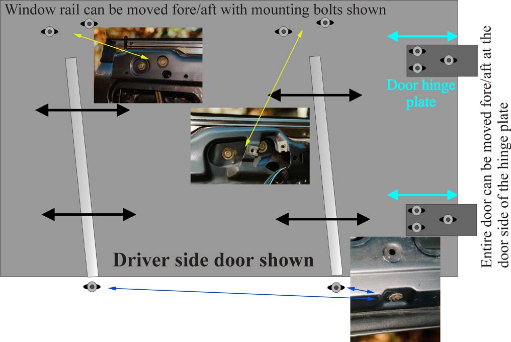
the rail seem to have two sliding/adjusting
bolts at the top and one at the bottom. Again, I did not do this
adjustment so there may be more bolts, especially at the top.
I just didn't see any other adjusting bolts for it. These bolts
all take 10mm hex head, ones at the bottom may require counter
hold. Loosening these bolts and sliding the entire window forwards
or rearwards should do the trick. This may be a two person job.
Go slow, little adjustment at a time and see the general fit before
making more adjustment. Always a good idea to mark where things
were before you started to mess with them. I used a fine point
permanent marker and made an outline of the washer/bolt position
before loosening them, just in case.
2) Window top tilting angle adjustment: There seems to be a single
adjustment point to correct the alignment if your window is too
high at the rear (as was my case) or too high at the front. The
amount which can be adjust by this is VERY little, I maxed out
the adjustment and the relative change in the window position
was very small but adequate. This is one of the reasons why your
door should be in the correct position to begin with. Referring
to Figure 2A ,
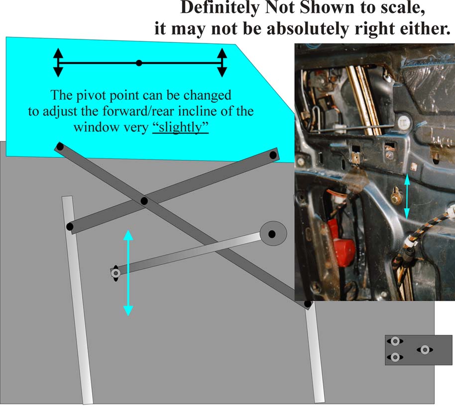
there is an adjustment bolt at
the midway down the door to the rear. This slides up or down to
change the relative pivoting point for the window up/down mechanism
(or so the technician states). If you want the front to come up,
you lower this bolt in it's sliding hole, if you want the front
to be lowered, you slide it up. The adjustment was hard to do,
as the pivot arm felt pretty solid when the bolt was loosened.
What I did was to loosen the bolt, move the window up/down with
the electric switch, you'll see that the bolt will move in the
sliding hole as the window goes down/up. You secure it when the
bolt goes up/down a little and see what that has done to the alignment.
The Figure 2B
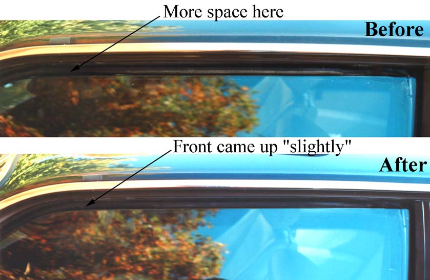
shows the before and after shots.
The adjustment was maxed out, the effect was very small. The top
panel in Figure 3 shows that the gap between the window and the
gasket is bigger at the front than at the rear before adjustment.
After the adjustment, this is reduced quite a bit (bottom panel).
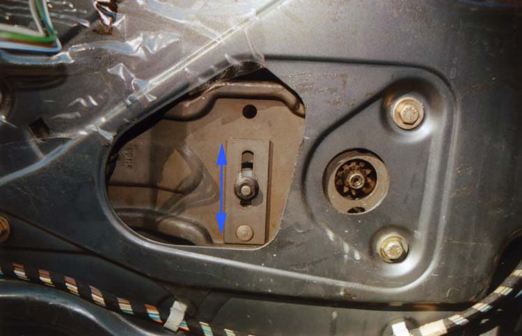
3) Window angle (in relation to the body) adjustment: To adjust
the rear part of the window, lower the window about 4 inches until
you see the adjuster through the access hole to the upper rear
of the door as in Figure 3.
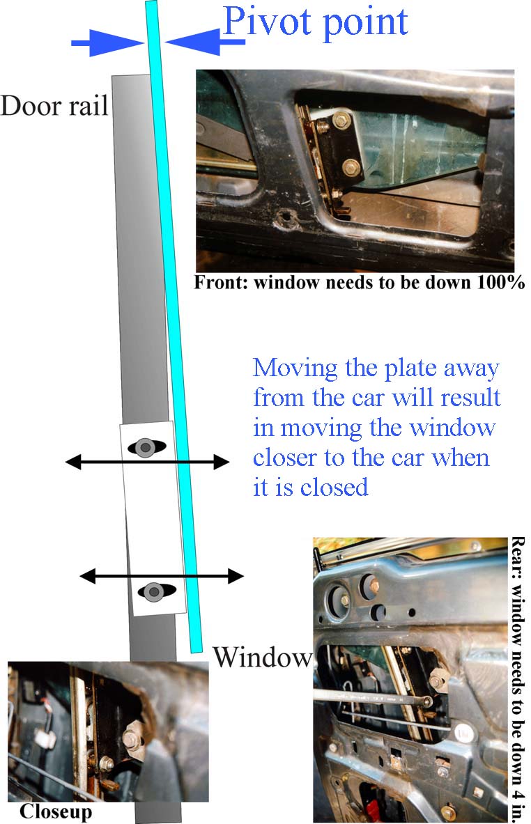
The two bolts for this
are facing toward the front of the vehicle, you need a 10mm box
end wrench or something with reach and clearance. As it's shown,
the pivot point for this mechanism is the window sill, meaning
that if you push the adjust plate away from the car, it results
in pulling the top end of the window closer to the car, and vice
versa. The adjuster plate for the front of the window can be accessed
by lowering the window all the way, and through the access hole
to the lower front of the door, see the figure for details.
4) Window stopping height control: This is real simple adjustment,
I would do this the very last when everything else is well adjusted,
an icing on the cake, so to speak:-) There is a locknut in the
mid front section of the door which secures a bumpstop that slides
up and down by adjusting the position of this nut, see Figure
4. 
You must lower the window about
an inch or so by your window control switch, adjust this bump
stop, then run the window up until it stops. If too high/low,
adjust again. Very small adjustments are usually required. This
adjustment usually takes the most finess since you are trying
to strike a good balance between the door closeability and the
window sealing/minimizing wind noise.
The whole process should take you a good amount of time, again,
there's never a perfection when it comes to this adjustment process.
It's a balance... you can make the window seal like a vault, but
will have hard time opening/closing the door, and vice versa.
There's a LOT of trial and error involved here, very much an art/Zen,
whatever you want to call it:-) Good luck with it, I know I thought
I did a good job on the adjustment but I could do with a little
more... My thanks go out to JG Barnes and J Seaway for some information
from previous posts found on Lars' archives, also to Al Sutlick
for detailed instruction on interior trim removal procedure a
while back.
Adding
a Dome Light Over Center Console Area Russell g Overton
It should be noted this modification was performed on a 1984 633
Csi using a dome light from a salvage 1985 325. The dome light
on the E 30 looks like a smaller version (single lamp) of the
one over your left shoulder in the E 24. The E 30 dome light will
fit, with internal modification, into the access panel of the
sunroof. No cutting or altering of any visible surface is necessary
in order to perform this modification. The dome light fits perfectly
into the hole as though it were made to go there.
The advantages of doing this are great.
At night you can see your ignition switch, you can see the OBC
so you can enter your lock out code, and you can pull off to the
side of the road, turn the light on and read a map.
Once you have the parts and tools together
it should take about 45 minutes from start to finish.
Parts needed:
1. dome light from an E 30 (3 series 1984-1990). There are two
mechanical styles of this dome light. The one needed for this
project is the style that rotates the contact for the lamp, not
the one that shifts the contacts from side to side. Cost at most
local salvage yards: $2-5.
2. Approximately 4 feet each of three different colors of wire
(copper #16 gauge), or remove enough of the wiring harness from
a salvage E 30, presumably the one used for the dome light itself.
3. Three splice connectors and 3 female spade terminal connectors,
or the originals from a salvage E 30.
4. Electrical tape and/or insulating covers to go over the above
mentioned connectors. These connectors must be insulated. Points
of ground will be very close to them, the dome light relay lists
for $80 and this circuit feeds into the OBC. Please make sure
no positive wires can be accidentally grounded.
Tools needed:
1. Small fish tape or stiff wire (about 5 feet long).
2. Wire strippers and cutters.
3. Small awl.
4. Small flat blade screwdriver.
5. Small needle nose pliers.
6. Bench grinder or other suitable means of abrasion.
7. Electrical tester (one that will check both continuity and
DC voltage)
Procedure:
1. Disconnect ground from battery (see notes above about the delicacy
of this circuit).
2. Release and remove existing dome over left shoulder. Be sure
to note which wire is positive, which is ground all the time,
and which is switched ground. If necessary make this identification
before disconnecting the battery.
3. Remove access panel for sunroof, it simply snaps out.
4. It is not necessary to remove the header panel at the front
of the head liner, but this could be done to make fishing the
wires easier. All that is necessary is to pull down gently on
the panel and cut a hole just large enough to feed the wires through
in the portion of the headliner BEHIND the panel. Be careful to
make sure the hole is far enough back that it would never rip
into a visible area. Also make sure the hole is in a direct line
with the existing dome light.
5. Carefully push a straightened fish tape or stiff wire from
the opening of the existing dome light to the hole you just cut.
6. Attach the three color coded wires and pull enough into the
access for the existing dome light to allow for making connections
and allow enough wire to lay in above the header panel and that
will allow for making the connections at the access for the sunroof.
Lay the wires into place and allow them to protrude from the sunroof
access.
7. Using splice connectors, splice the new
wires into the old noting which is positive, which is ground all
the time, and which is switched ground.
8. Install the spade connectors on the other ends of the new wires
at the location for the new dome light (sunroof access).
9. The only problem with the new dome light is that it is too
tall for the opening. The motor for the sunroof is at that location
and clearance is very tight. Very carefully remove lamp, contacts,
and retaining clip from new dome light. You will probably have
to use an awl or small screwdriver to release the metal components
from the acrylic housings.
10. Using a bench grinder shave enough of the acrylic housings
to allow the dome light to fit flush into the opening. The goal
is that when reassembled it will snap in place and be flush. The
side with the retaining clip must mount towards the passenger
seat.
11. The retaining clip and contacts will now be too long. Slightly
heating if necessary to prevent stress, you now need to straighten,
cut, and re-bend these components to fit the modified dome light.
You will need to make these adjustments where they fit into the
acrylic housing.
12. Reassemble the light, securely fasten the spade terminals,
making sure they will not ground to any of the components above.
Snap your new light into place making sure the wires are not in
the way of any moving parts. At the original dome light use your
tester to make sure the positive wire is not grounded.
13. Snap the original dome light back in place, reconnect the
battery, wait for nightfall, open the door and find your ignition
switch without having to feel around.
Note to the wise:
When obtaining your new dome light it might
be a good idea to purchase an extra unit just in case you have
a fatal accident during steps 9-11.
Lighted
Rear View Mirror Install - "Michael
Barrett"
This has to be the second easiest modification
your can make, right after adding floor mats. The parts and materials
needed are:
1) Lighted rear view mirror from E30 coupe (BMW part number 51
16 1 906 525). 2) 3-4 feet of 16 gauge wire 3) Phillips screwdriver
4) Sharp knife (x-acto or similar) 5) Wire connectors of some
sort (see text below) 6) Coat hanger (the wire kind)
The mirror lists for $160 from BMW; I got mine from VOB BMW (they
advertise in the Roundel) for $115. Used prices, I'm guessing
are probably in the $15-35 range. The part number is stamped on
the back, so if you get a used one, you can still be sure it is
the right part.
The first part of the procedure is perhaps the scariest. Grab
the old mirror by the arm that connects the mirror to the roof,
and pull it off. That's right, just pull. It doesn't take as much
effort as I thought it would (I imagine it's a safety feature).
The mirror is held in place by two spring-loaded pins. You'll
see them on the new one, as well as the plastic wire connector
for the lamps.
Prepare the new mirror by removing the plastic connector on the
end of the white and black wires. Depending on how handy you are
with implements of this kind, you may want to solder the wires
from the mirror to the two new lengths of wire, and cover with
shrink wrap, although I just used wire nuts. I would have gone
the first route, except I got caught up in the excitement and
wanted to get the mirror installed.
Next, remove the four screws (two on each end) that hold the passenger
side sun visor (with the lighted vanity mirror) to the headliner,
and remove the visor. Be careful when you remove it, since you
want to make sure you also pull the wires for the lighted vanity
mirror out of the openings on each side; if you're not careful,
you may find yourself having to fish around inside the headliner
to get them out.
Once those are removed, take the wire coat hanger and fish the
wires from the new rear view mirror through the opening where
the rear view mirror goes to the openings from the visor. There
is a channel that runs along the front edge of the headliner just
inside the top of the windshield.
Now install the new rear view mirror, simply by pressing it in
up into place. It takes a little bit of effort, but nothing that
requires brute strength. I found that if you put one of the pins
in place first, and then push up on the opposite side, it works
fairly well. Then splice one of the wires from the rear view mirror
to each of the connections for the visor mirror. Again, if you
are slick, you can probably remove the existing connectors from
the end of the vanity mirror/visor wires, and reinstall the connector
over the joined wires. Me, I just cut each of the wires for the
visor mirror and, using two more of my trusty wire nuts, connected
the wires together. I don't believe that it matters which wire
goes where, since you are just completing a circuit, but the inboard
visor wire is the positive, and the outboard visor wire (closest
to the A pillar) is the ground.
Once your wires are connected, push the wires and connectors up
into the channel, and re-attach the visor to the headliner. You're
done. With this set-up, the map lights will only function when
the car's lights are one (since that is the only time that the
vanity mirror works). Personally, I think this is wise, since
it avoids the possibility of a dead battery from the light being
left on in the daytime (not that my son who likes to read in the
car would EVER do that, right?!) I originally thought about connecting
to the power sunroof switch/motor, but it does not appear that
the front channel above the rear view mirror opening has easy
access to the sunroof area. The beauty of installing it as set
forth above is that the headliner doesn't have to be removed,
and its a straight shot from the center opening for the mirror
along the front channel, so that fishing the wires is easy. In
fact, I think it took me longer to type this up than it did to
actually install the new mirror.
Interior Door Panel/Trim Removal
('85 US635CSi) - "Louis P.
Hodgson"
With a very small screwdriver (jewelers
type is best), gently pry out the exterior mirror control switch
from the door handle (pry out plastic insert or the passenger
side). Disconnect the switch from harness, keep it safe. Inside
the hole you just opened up, there should be two Phillips head
screws securing the handle to the door, remove them. Use magnetic
head screw driver to avoid losing your screws. Once those screws
are out, you should be able to pull the upper part of the handle
toward you, pivoting it at the base of it (make sure the door
storage compartment's lid is in up position), it should come off...
there's two retaining tabs at the base of it which locks the handle
into the base of the handle. As you pivot the thing toward you,
they should pull up and out.
The upper black window sill part (molded
plastic) is secured on by two screws, one at the front, one at
the rear. The screws are in a position such that you won't see
it with your door closed. You remove those screws, the black molded
plastic part should pull off toward you (this is sort of kept
in place by the silver window sill part and the black door locking
pin on the far end of it, you'll just have to pull gently toward
you and sort of up to dislodge the pin from the molded assembly).
There are 4 screws securing the bottom panel to the door, two
screws are revealed by removing the handle section (which you
just did), and the other two are in plain sight when you flip
open the storage compartment lid. Undo those screws.
The rear portion and the bottom portion
of the bottom panel are secured onto the door panel by those plastic
pop rivets/clips, undo them carefully by may be using something
flat as a wedge. The very front of the bottom panel has a tab
that goes into the door frame to secure. To undo it, you pop out
all the clips and pivot the whole thing toward the front of the
car and slide/pull out. The middle panel is held in place by the
trim piece around the door release lever (you slide this off,
pull toward the rear of the car a little to unlock it and pull
up...$3.75 if you break it:-), and one plastic pop rivets on either
end (front and rear). Once those are out, you can remove the panel.
There's a plastic vapor barrier underneath
the whole thing. Yours may still be intact and original. They
tend to shrink and get rather brittle with age. Mine ripped completely,
so I just used some heavy duty clear garbage bag, cut to size
and duct taped it in once I was through with everything.
Assembly is reverse of removal.
Speedometer Repair - "Thom Pomeroy"
Hello Group,
A few weeks ago I posted regarding a failed odometer and where
to obtain the small plastic gear that had cracked in order to
repair it. A couple of you asked me to give you an update on a
source for the gears and the difficulty of the repair. Here it
is:
I obtained the gears from Continental Imports
(352-377-6604 or http://www.continentalimports.com/
), thanks to Jim Booth's referral. The salesman, Scott Brotherton,
recommended replacing the two rubber (yes, they really are rubber)
gears in the drive mechanism as well as the plastic gear that
had failed. I ordered all three gears to the tune of about $70.
Ouch! This is quite honestly the first time in 12 years of BMW
ownership that I felt the parts were grossly overpriced. When
the parts arrived, it turned out that one of the rubber gears
was incorrect, so I elected to replace just the failed plastic
gear as originally planned. Returning the two rubber gears brought
the cost down to a more reasonable $25. The wisdom of this decision
is yet to be determined!
Side note: Continental Imports was very
helpful and I had no problems returning the unused gears. They
are also a dealer/repair facility for Blaupunkt and Becker stereos.
When I asked for some stereo advice, I was surprised that Scott
did not try to sell me a new amplifier, but recommended that I
keep my current factory amp. I felt that I was getting very honest,
fair advice. Quite refreshing.
Replacing the gear is definitely NOT for
the faint of heart! Removing the instrument cluster is not difficult
if you know where to find all the fasteners. Some of them can
be very elusive unless you have a manual or other source (read
someone who's done it before) to tell you where to look. Once
the instrument cluster is removed, you must remove the speedometer
from the cluster. Again, this is not terribly difficult, but it
gets pretty tedious from this point on.
The small plastic gear that fails is molded
on a brass sleeve and is pressed on a steel shaft. The fit is
very tight. I have replaced these gears in VW odometers and the
plastic gear presses directly on the shaft without the brass sleeve.
In this case, the gear can be removed and carefully pressed on
by hand. In the case of the BMW, I had to gently tap it on with
a small hammer. Even that is not a simple as it sound, because
the opposite end of the steel shaft bears against a plastic fitting
in another part of the drive mechanism. This requires further
disassembly of the drive in order to expose this end of the steel
shaft so that it could be placed against something solid while
driving the new gear on. Otherwise, you would just drive the shaft
through the plastic parts at the end of the shaft opposite the
gear. I also had to come up with something to support the whole
speedometer assembly while doing this. If you want to update your
odometer reading to reflect the lost miles since the gear failed,
there is more disassembly and tedium involved.
Someone had mentioned that one of the authorized
VDO repair shops will do this for around $125. I'd say, unless
you enjoy this sort of thing and don't mind chancing serious damage,
it would be money well spent. I was able to do it myself, but
like I said, I've done several VW odometers and this one still
made me very nervous.
Thom Pomeroy 85 M635CSi
Front Seat
Swap - Carl Lee
It had always crossed my mind that swapping the 2 front seats
would be a good way to preserve the condition of my interior since
the only real wear was in the drivers seat. Naturally I turned
to the forum for tips and the experience of others before me.
I found an article "rejuvenate those front seats" to
be just what i was looking for but I was put off by talk of cutting
wires and what a PITA it was to remove the seat backs. After getting
started i realized there must be an easier way and here it is.
Each seat is connected to the base by 4 screws and 2 cables. I
would start by disconnecting the battery and then all connections
under the seat. there is 1 big plug, 2 smaller ones mounted towards
the back of the seat and 1 for the power head rest motor in the
seat back. Then remove each seat from the car complete by removing
the four bolts connecting the seats to the floor and lift the
entire seat assembly completely out of the car.
Remove the triangle shaped plastic covers at both sides of each
seat. You will see that black cable that comes from below the
seat go into a metal housing on each side. Remove the screws holding
the assembly to the side of the seat and pull the entire assembly
from the side of the seat. this is the gear that makes the seat
back go forward or recline. I placed each assembly in a plastic
baggie while still connected to the cable and taped it off so
dirt can get in and small parts can't get lost. Now remove the
four bolts connecting the seat bottom to the frame and you can
remove the entire seat assembly. Now you can swap the seats themselves.
Reassemble the seats before you put them back in the car and don't
forget to swap the plastic side skirts that connect to the base
of the seat. Also, when you reconnect the side gear assemblies
made sure you push the seat back far enough so the teeth are engaged
in the gear. Lastly make sure you reconnect the power cables under
the seat and use cable ties to hold them in position. Bolt everything
back down and voila! You now have a brand new drivers seat.
If you have any questions or comments feel free to contact me.
Un-clogging
Sun Roof Drains - Carl Lee <countchocula1@hotmail.com>
After a torrential downpour I was shocked to see a pool of water
on the rear passenger side floor of my car. My sunroof had never
exhibited any signs of leakage before. Once again I turned to
the big coupe groupe pages for help but was turned off by talk
of having to pull down part of the headliner to get at the rear
drains to unclog them. My main concern was that once i pulled
down the head liner it wouldn't line up so nice and tight as it
is right now. There had to be another way and sure enough I found
one but I have to warn you, this is not for you if you lack patience!
The front drains are pretty easy. I used a heavy 3 wire electrical
cable, the kind that has 3 individually wrapped wires which are
then all wrapped together with a plastic sleeve. I just happened
to have a large length of this laying around but you can buy this
stuff by the foot at Home Depot or a hardware store which is where
you will probably need to go for the second piece you need which
is a short length of copper tubing. I used a 15"toilet supply
line. For the front drains you don't need the copper tube, just
snake the wire down the drains. The rear drains are a challenge
but it can be done, believe me.
First, open the sunroof and pull down the headliner so it un-clips
from the sunroof top and slide it all the way back into the roof.
Now open the sunroof so just the back part lifts up. Take a small
bright flashlight and look through the space between the roof
and the headliner. the rear drains are about 1 inch in from the
rear corners of the sunroof but you can't see them. What you can
see are these 2 rectangular tabs that stick up from the car. there
is 1 at each side of the rear of the sunroof opening. As you look
towards the rear of the car the left hand drain is at the immediate
left and below the rectangular tab and the right hand drain is
to the immediate right and below the right hand rectangular tab.
(SEE ATTACHMENT)
Take that copper tube and feed the end of your cable though it
so it sticks out of the other end. Using the copper tube as a
guide gently poke around in the area described above. With a little
luck and time you will be able to start pushing the cable through
the drain tube. If the cable stops moving try twisting the cable.
if you have already pushed through a good amount of cable check
the openings at the rear of the rear windows. The sunroof drains
exit there and when i took a look I could see the end of the cable
and there was a mass of black muck and the trapped water had drained
out down the side of the car. If you have trouble finding the
drain opening in the sunroof try putting a slight bend in the
copper tube. Don't forget, patience and persistence are the words
of the day for this job.
Door interchange
information--pre and post 82 U.S. models
- "Gene
M."
For those folks who may some day be looking to replace a door,
the parts CD shows the same part # for a door for an 83 &
later E24 and an 82 E24. (83 is the changeover to the E28 based
frame so body pieces like front fenders show different part #--larger
wheel flares after 82).
I picked up an 82 door and have compared it to the 83 & later
door (U.S. models)and there are a couple of differences. The interior
door handle pulls are different (the 82 doesn't have the power
mirror switch in the handle--it is a separate unit like the E28
switch) and so where the int. door handle pulls screw into the
door on the top is in a different location on the door. There
was some slight modification to the sheet metal in this area after
82, but it looks like it shouldn't be too difficult to make the
modifications to accept the 83 & later type door handle. Some
grinding and a bit of bending in a area of about 2 inches x 3
inches.
The manner in which the bottom interior panel of the door attaches
is also different. A slot is needed in the lower front of the
door for the 83 & later panel to slip into--the 82 door doesn't
have the slot. Also the 3 screw holes on the top of this lower
panel on the 83 & later do not line up with any pre-existing
holes on the 82 door. The int. door handle on the 82 is mounted
in a different location and is a different style, but the 82 door
does have the rectangular cut out to mount the 82 & later
style int. door handle.
So, if you need to replace a door on an 83 & later, don't
get an 82 or earlier door unless you are willing to make these
modifications.
It looks like if you are replacing a door on an 82 or earlier,
you should be able to use an 83 & later door without having
to do much modification except for the inserts to accept the 4
screws that hold the the armrest in place. The long rectangular
hole to accept the 82 power mirror control and the cut out to
accept the 82 int. door handle are in the 83 & later door.
One other note, the wiring connectors for the various components
inside the door may be different for various model years.
Plastic
Door Clip Replacement - "Gene
M."
On the bottom section of the inside door
panels are the plastic clips (white or green) that get pressed
into the holes in the door. These frequently break off and the
door panel doesn't stay flush.
To replace these, they need to be twisted
in and out. The back of the clips that is inside the door is round
with an "V" shaped cutout, with one leg a little longer
than the other. Take a look at the replacement clip to see what
I mean.
The "trick" to getting these in/out
is you need to slide the clip over in the door panel hole until
an edge on the longer leg of the "V" is at the
edge of the hole, bend the clip over so the tip of the "V"
starts to protrude and then twist so that it threads its way out.
Using a pair of
wide nose pliers will make this easier and less likely to damage
the clip. A pair of needle nose can be used to grab the remains
of a clip that has had the tip break off.
Installation is to put the long tip of the
"V" into the opening and then twist it in.
Power
Door Mirror Connector and Mirror Assembly/Mount Removal - "Gene
M."
The power mirror connector to the door wiring
harness is not visible. The connector is a flat, 4 prong connector
that is up inside the long triangular mounting arm that goes inside
the door.
To undo the connector it is best to remove
the mirror assembly from the large trangular arm that goes down
into the door. You first need to remove the plastic inside cover
that covers the visible triangular piece at the front corner of
the door window. Remove the small phillips head screw on top of
the triangle and then slide the plastic piece up toward the apex
of the trangle--there is a plastic tab on the plastic piece that
slides into the mounting plate so do not pry straight out. Once
the plastic cover is removed, remove the 3 large phillips head
screws that hold the mirror assembly onto the mounting arm and
the mirror assembly can be removed with the wiring attached. The
connector will be about 4 inches down and it may take a little
wiggling to get it to come on up.
To remove the long triangular mounting arm
that slide down the door, you need to remove the inside door panels.
Up on top of the door by the shiny trim there are two 10mm head
bolts, and about half way down the door there is a 13mm nut that
is mounted on a bolt that has a slotted head--this nut and bolt
are inside a hole in the inner skin of the door panel. You need
to remove the nut and washers and then use a slotted screwdriver
to remove the bolt from the mounting arm so that there will be
clearance to slide the arm straight up out of the door. There
will be a lot of gooey strip caulking around the mounting arm
so you may want to have some on hand when reinstalling.
You can disconnect the power mirror connector
when you remove the mounting arm with the mirror assembly still
attached (you can barely see the connection joint and you can
separate the joint), but you will not be able to reconnect the
connector without removing the mirror assembly from the mounting
arm and fishing the wiring from the harness up inside the mounting
arm. I found this out the hard way.
BTW, removing the mirror assembly will NOT
give you access to the mirror motor or gears. The mirror glass
needs to be removed with a heat gun to gain access to those parts.
Instrument
and Dash Panel Bulb Replacement -
"Bill
Wolf"
You need to remove the panel that the control
is mounted in. The bulb may have just fallen from the housing
that it sits in. It's a very small bulb. I used Sylvania #2721.
If it fell out, the housing may be cracked it can be easily fixed
with a bit of plastic cement.
To get the front panel out, remove the plastic
vertical trim between the instrument pod panel and the ac heating
and ventilation controls. Remove the two screws. Pry carefully
out hazard and ac switches. Remove the two screws, a bit above
and below the upper and lower holes. I unplugged the switches
from their connectors to give me more visibility. I also fed the
AC connector back in the hole because the wiring harness length
was constraining. You may also need to remove the rear window
defrost switch to get the panel out far enough. Remove the temperature
and blower control knobs and carefully pry off the pictogram in
the lower left corner. The screws two each behind the temp &
blower knobs I had two screws behind the blower knob and none
behind the temperature knob, and two screws behind the pictogram
lower left corner hold the whole mechanism to the face plate.
Also to remove the face plate you will have
to remove the slider knobs. They are 3 pieces, the outer black
part, a translucent mid piece, and a white backing part. All 3
need to be solid to stay in place. They mount to the sliders by
pressure. The sliders have 2 small tongues that hold the knobs.
BE VERY CAREFUL WITH THESE -ask how I know. There are I think
3 bulbs back there. For some strange reason I just assumed that
these were LEDs and didn't investigate their replacement? But
I don't recall how much needs to be removed to get at them. Not
much I think. Also while your at it, it's a good time to replace
all the bulbs in there. I only found two behind the heating and
ventilation panel Esp the 2 cluster bulbs, upgrading them to 5
watt bulbs from 3 watt for better night driving. I found the instrument
panel to be a whole new project
Door lock mechanisms - "Jill Cheney"
I just did this thankless job & the
topic just came up on bimmer.org, so I thought I'd write it all
down & submit it to the group in case anyone would benefit
from my pain.
I initially realized I was going to have
to tear apart my door when the metal cover came off the keyhole.
About 2 months later, the drivers door lock stopped operating
from the key at all. I locked and unlocked my car from the trunk
for months while I put this off. While I was procrastinating,
I heard a spring pop & then my interior door release would
not return by itself. I figured 3 annoying faults was enough to
warrant pulling apart the door...
Firstly, if the metal trim is missing from
the lock on your car - then sorry, the only way to fix it is pulling
the lock & probably replacing the cylinder. The trim piece
is only crimped on & there is no effective way to put it back
on from the outside.
Secondly, there is evidently an "earlier"
& "later" lock cylinder design. The early one is
mostly pot-metal & prone to failure. The later one makes more
extensive use of ABS plastic for little lever parts. Its obviously
superior in its design, but parts from the two cylinders are not
interchangeable. It is possible however to re-key the newer cylinder
with wafers from your old lock. I'll get more into this later.
It may help you to disconnect the battery
before starting. My power locks were always switching while i
fumbled with the mechanism. I dont have my OBC code however, so
I didnt disconnect the battery.
Procedure
1: Remove interior trim pieces
1a) Carefully pry out the mirror control
switch from the door handle. It will reveal 2 screws - remove
them both then pull the top of the handle towards you to disengage
it from the armrest.
1b) Remove the 4 screws on the top edge
of the armrest. 2 were revealed by removing the handle, 2 are
accessed by opening the compartment in the armrest.
1c) STARTING AT THE BACK, pop out the clips
that hold the lower panel to the door. Once they are out you must
swing the panel out from the back because it engages the door
with a swing-type catch at the front of the door. Removing the
panel by starting at the front of the door will break this off.
1d) carefully remove the surrond from the
door release handle. It slides off to the rear. It is pretty tight
& easy to break if the plastic is deteriorating. Be firm but
careful with this part.
1e) pop the clips on either end of the middle
upholstered trim panel. swing it up from the bottom & pull
it down & out from under the top piece.
There is no need to remove the top panel
from the door. No additional work space is revealed & the
part isnt designed to be removed with the lock plunger sticking
up through it. Just leave it be.
Procedure 2:
Remove Lock Cylinder & Lock Assembly
NOTE: dont disassemble any more of this assembly than you have
to to get it out. You will want to study it on the workbench to
make sure you understand how it works.
2a) Remove as much plastic sheeting as needed
to access the mechanism.
2b) Trace the lock heater wiring and disconnect
at the plug.
2c) Take off the tiny clip which connects
the rod coming down from the lock to the door catch mechanism.
Dont lose the clip.
2d) Remove the 8mm nut which attaches the
arm to the inside of the exterior door handle. Take out the arm.
2e) There is a U-shaped clip that secures
the heater element/power lock swich to the lock cylinder. Press
out the U shaped retaining clip toward the back of the door. This
clip is difficult to see at first. The easiest way to get it out
is to pry at the front & then get a screwdriver & push
it out. It will invariably fall down into the door cavity and
you will have to fish it out. You should be getting good at this
because the little clip from step 2c probably already fell down
there.
2f) The heater element/power lock switch
must be moved ouwards along the axis of the lock cylinder. You
must finesse the heater element/switch assembly to loosen it up
from the cylinder. When you get the whole thing out you can study
this action more carefully. Basically, the cylinder slides inside
the hole in the center of the heating element.
2g) Once the assembly is loosened, rotate
the whole thing 90 degrees counter-clockwise (drivers door) to
disengage the lock cylinder assembly from the exterior door handle.
2h) It is now apparent how the electric
lock swtich attaches. Go ahead & remove it so that you can
move the whole assembly to the workbench.
If you need to fix the lock cylinder, skip
to precedure 4. If you are replacing the exterior handle gasket
or fixing a broken handle, go on to procedure 3.
Procedure 3:
Dismounting the evil exterior door handle.
3a) Remove the nut attaching the handle
to the body. This nut is located at the front of the handle assembly.
3b) There is a retaining bar which runs
between the two pivot points of the door handle (note that the
handle & its surround are permanently attached to one another).
There is a clip by the rearward pivot which secures the retaining
bar. Pry this clip off, trying not to destroy it.
3c) Slide the retaining bar towards the
rear & out. The handle will probably fall off now. Be careful,
if this hits the ground it will probably break.
3d) Replace the gasket or handle or whatever.
Procedure 4:
Replacing the lock cylinder NOTE: This procedure
describes the "early" design with the metal retainer
& pot-metal lever arm. I didnt have to tear up a newer design
lock.
4a) If the chrome surround for the key-hole
has come off & you still have all the parts, you may be able
to re-attach it by taking a nail & re-crimping it to the lock
cylinder. I couldnt, but maybe you are really skillful.
4b) slide out the metal retainer which secures
the oblong rod-actuating lever to the lock cylinder. Take special
care to observe the how the sping underneath it is seated. You
will have to put it back because it will sping off. My metal retainer
was mangled, causing my cylinder to spin freely & not actuate
the lock. I was not able to fix the retainer, I scavenged one
f rom the used mechanism I had.
4c) Separate the heater/swich element from
the cylinder itself. The cylinder may fall apart in your hand
or it might be stiff as heck. Check for broken metal tabs at this
time.
4d) there are 4 main parts to the cylinder
assembly:
1) The rear cap (which attaches with a
evil little ball bearing & spring - think of a ratchet/socket
retainer) which can be finessed off.
2) the middle housing (mine was yellow
in color) which simply pulls of.
3) the main housing, which the other pieces
group around. &
4) the lock cylinder itself with its rubber
o-ring & integrated trim piece. It is easiest to disassemble
this mechanism with a key in the lock (even the wrong key) as
it will keep the wafers from falling out.
4e) Once this is all disassembled, compare
the old & new cylinders. Note how sliding the correct key
in the correct lock causes all the wafer to retract? Good, this
is what allows the key to turn & what is going to allow you
to reassemble your lock. You can CAREFULLY transfer (one-by-one)
your wafers to the new cylinder & this will re-key your new
cylinder to work with your car's key.
4f) Place the key in the fixed cylinder
and start stacking all this stuff back together. Each part only
fits in one way, so pay special attention when you take it apart.
The worst part is the rear cap where you must fiddle with the
spring & ball to get it to stay.
Step 5:
Reassembly notes
a) First study the action where the lock
cylinder slides in & out through the heater/switch assembly.
b) When putting the lock cylinder assembly
back in, note that you put the assembly in at the 90 degree position
(parallel to the ground) and then rotate it to engage the handle
mechanism.
c) the heater/switch assembly must slide
completely home (all the way to the inside door skin) before the
U-shaped clamp will slide back in.
This whole process took me several hours
because I had to stop at many stages & carefully study the
assemblies.
Good luck!
Power Seat Stuck All The Way Back - "Gene M."
If you have a power seat that is all the way back and will not move forward or backward more than about an inch, this may be your fix. My passenger seat on my 87 L6 had this problem and I finally got around to diagnosing and fixing it.
On the seat rail tracks, there are metal gold colored stops that should be clipped on the top, back of each rail. If both of these stops come off, the seat will go back too far and then lock up occurs, they will only move about an inch forward and backward and there will not be any visual clues as to why the seat will not move, even if you take the whole seat out of the car.
In order to fix this, I had to unbolt the seat and push it out of the way, and then remove the drive gears from both rails (that's why the seat had to be unbolted, to gain access to all of the nuts and bolts that need to come out--no way to get at these all with the seat still in place).
The outside gear is mounted with the drive gears for raising and lowering the seat bottom, so all 3 gears for the seat cushion are disengaged at this point. Next, the cross support for the front and back of the seat cushion need to be pulled up all the way, and now the frame will slide forward from that "locked" position. Until I lifted these cross supports up, the seat remained locked.
The stops must be put securely back in or else the clips can just pop off when you move the seat all the way back and you'll be taking the seat apart again.
Preventive measure is to make sure those 2 stops are clipped in place and the clips are tight. They are clearly visible when the seat has been adjusted forward--they sit right on top of the rail. If you only have a clip on one of the rails, buy the other one and put it on.
BTW, all E24 power seats do not have the same rails and stops. My 86 635 with sports seats has a fixed stop that is part of the rail.
Trunk Lid Springs M"Gene M."
If you open the trunk lid on your 6er too high, the ends of the trunk springs may come out. If this happens, you will not be able to close your trunk and the trunk lid will be very heavy as it is lowered. Do not try to force the trunk lid closed and do not try to bend the springs to get them back in.
It is difficult to identify these parts by description--I printed out the parts fiche but the portion of the trunk hinge on each side that the ends of the springs fit into ("pivot arms" is what I'll call them) are not shown.
In order to get the spring ends back in, you need to open the trunk lid as far as possible to release as much tension on the springs as possible . Make sure the "pivot arm" on the side where the spring came out is correctly oriented to face forward like the other side (look closely at the side that still has both spring ends in place for comparison). I used a crowbar with the end wrapped up to prevent scratches to the paint to get the spring ends back in place. The spring ends do not go in easily.
Once the spring ends are back in position, you need to make sure the trunk lid is not opened high enough to release the spring ends again. I screwed up a couple of times and opened the trunk lid and had to go through the process again.
In order to keep this from happening again, you need to prevent the trunk lid from opening too high. I placed a rubber "stop" between the hinge stop that I made from industrial Velcro with thick rubber on one side just in case I need to ever release the tension on these springs, I can then remove the rubber stop and open the trunk to its too high position.
Until you get in there and take a close look, it may be hard to understand this fix. I did this fix in 2000 in my 83 633 and I have not had a problem since then. I have also installed this rubber "stop" in my other 6ers as a preventative measure. If you have to reinstall the spring ends, I do not think you will want to do it again. Without installing the preventative rubber "stop", it is too easy to lift the trunk lid beyond the "spring has sprung" point.
Oh yeah, remember to not climb completely in your trunk when performing this fix unless someone is around to let you out if the trunk lid drops down and latches. Seems obvious, but strange things can happen when your wrestling with a potentially frustrating job.
Gene M.
Sunroof and Headliner Panel Removal - Author Unknown
1. Leave your ignition off and use the manual Sunroof operation procedures (This will lessen the chance of significant damage to your drives worms): use the sparkplug wrench to loosen the large nut on the motor. Then use the allen wrench tool to open and close the Sunroof by turning the fitting within the large nut. Wedge the allen wrench in with some paper wadding or such to keep it from falling down every 15 seconds (drove me NUTS for a while).
2. Open the Sunroof. From outside the car, unscrew three screws from each side's guide rails and two screws from a bracket just behind them on each side as well. Make note of (mark) the position of the raised little ramp on each bracket. They are seperate pieces and will come free once you remove the brackets.
3. Carefully crank the Sunroof forward until it's just a couple of inches open and release the Headliner from it by pulling down on the front edge to release about six door panel type plugs/clips. Use of a strong, smooth, curved device to pry the clips away will prevent possible damage. Or just go to your parts store and buy a "Door Pannel Tool" (Approx. $8.00). Slide the Headliner all the way back.
4. Slowly closed the Sunroof. Remove three small nuts and washers from under each side of the Sunroof. They are arranged in a triangular pattern on triangular brackets. Release the brackets from the studs which are attached to the Sunroof. You may now remove the Sunroof by simply raising it from the inside and lifting it off from the outside. A second person used here or some nice shop blankets will ensure no uninvited "engraving" on your roof.
5. Pull the Headliner all the way forward. it will be attached to a transverse rail by a rod on each side. The rods can not be disconnected from the Headliner, but they can be disconnected from the rail by gently prying them down. A little clip and rod just disengage. You can now remove the Headliner.
6. To install: place the Headliner on its slides and snap the rod ends into the clips on the tranverse rail. (By the way, if you should have decided to remove the rail, remember to have the pointy ends facing forward when you re-install it.) Slide the Headliner all the way back.
7. Place the Sunroof back on the car. Before doing this, take the time to lube your rear seals, as this will be the last time you'll see them for a while (hopefull!) The end of the roof with "the little skis" on each side is the front. If you've moved the mounts just reposition them with the allen wrench crank. install the three mounting nuts and washers on each side.
8. This is a good time to adjust the Sunroof height if desired. The two screws that are attached to the sides of the triangular mounting plates are used to adjust the height of the rear of the Sunroof, which should be 1mm ABOVE the height of the roof behind it. The three screws across each front corner are used to control the front height, which should be 1mm BELOW the height of the roof infront of it. Loosen both sets of inner screws then turn each outer screw to adjust the height while pressing down on the Sunroof. Re-tighten the two inner screws on each side to lock the setting in. You won't believe the difference in Wind Noise a properly adjusted Sunroof can make.
8. Here's where my proceedures differ from the book's a little, but trust me THIS will save you mucho frustration. This extra proceedure is to re-engage the Headliner's followers with the rails on theSunroof itself, so that the Headliner follows the Sunroof when it's placed into the "Raised" position. Slowly, while pushing back on the roof to keep tension on the drive cables, crank the roof back far enough to re-install the guide rails and their three screws. Don't worry about the brackets yet. Now crank the roof about three fourths of the way forward.
9. GO WASH YOUR HANDS. Slide the headliner forward until the clips line up with their holes. A good pull on the front edge while gently pushing from inside will make this a bit easier. Snap all the clips home. Return the Sunroof to the full aft position.
10.. Being as you're in this "Mode", now would be a good time to remove the guide rails again and lube the rails and drive cables. My book recommends vasoline for the rails and light grease for the cables. Do this AFTER you're finished handling the headliner. This avoids the need for "Post Procedure Uphulstery Cleaner" to remove all your greasy finger marks. Replace the guide rails and brackets, AND their little ramps, returning the ramps to their original position.
11. Carefully crank the sunroof a little past full forward to make sure the headliner raises along with the sunroof. If it does, you're you're just about finished! Congrats. If it doesn't, return the sunroof to a "Closed" position, GO WASH YOUR HANDS, then disengage the headliner from the sunroof (Step Three above), slide it back, and pull it forward again while gently pressing upward on the rear of the headliner as it comes forward. Test the "Raised" position again. Done. (I Hope!)
12. Now re-tighten the large nut by the drive motor with your sparkplug wrench. It doesn't matter where in the cycle the Sunroof is, as it is the position of the drive cables that controls motor function. Turn on your ignition and see if it works.
SUN SHADE REMOVAL AND REPAIR - Gene M.
While pulling out the rear sun shade on my 86 635, it sounded as if the spring had sprung and the sun shade would no longer retract. I could not figure out a way to roll back up the shade while it was still in the car and the factory repair manual did not have any information on repairing/replacing the sunshade.
I was able to repair the sunshade after spending several hours and here is the procedure (now that I know the procedure, this would probably be about a3 hour fix the next time).
First, the rear shelf has to be removed from the car since the sunshade cannot be removed from the rear shelf while it's still in the car. This involves several steps.
REMOVAL OF THE REAR DECK
1. Remove both rear seats.
2. Unbolt the outside seat belt anchors (17mm) on both sides of the car and pass the latch and anchor through the metal guide that is mounted on the c-pillar (you need to remove the plastic cover on the metal guide to be able to pass the latch and anchor through the guide).
3. Unbolt the two 10mm nuts that hold each of the speaker pod covers so that the speaker pod covers can be lifted up (they have a hinge mount at the back so the front of the covers will lift up about 45 degrees). I removed the speakers and the speaker pod covers to reduce the weight. There are two8mm nuts that attach the cover to the hinge. If you don't remove the speaker pod covers, you will still need to unplug the speaker wires so that they can be pushed down under the rear deck.
4. Unplug the connector for the 3rd brake light. This connector is inside the 3rd brake light assembly and you need to pull out the reflector/bulb assembly so that the connector can be pushed down under the rear deck.
5. There are 5 or 6 plastic push in fasteners that hold down the rear deck(the same type that are on the interior door panels). I used a long screwdriver to work these out.6. The rear deck panel with the integrated sunshade can now be carefully pulled from the car.
REMOVAL OF THE SUN SCREEN FROM THE REAR DECK
When you turn over the rear deck, there will not be any obvious mounting hardware that holds the sunshade in place. It first seemed like it should push out from the back because of the top and bottom plastic trim that is on the face of the rear deck but it sure didn't feel like it wanted to budge. Do not start pushing and prying on the front plastic trim because it will not get the sunshade housing out of the rear deck. You need to do the following:
1. There will be six 7mm nuts under the rear deck--4 hold the hinges for the speaker pod covers and 2 hold a couple of arched metal clips. Remove all of these nuts and the arched metal clips. The rear deck now has some flexibility in the crease where the bottom plastic trim of the sun shade housing runs along the rear deck.
2. Run a putty knife or plastic scraper between the bottom plastic trim of the sunshade housing and the rear deck to loosen this up. The bottom plastic trim needs to be worked to go BEHIND the rear deck so that flexibility in the crease under #1 is important. I started in the middle and worked my way outward since the corners really don't want to budge. I used a putty knife to persuade the corners.
3. Now run the putty knife or plastic scraper between the top plastic trim off the sunshade housing and the rear deck to loosen this up. You will eventually be able to loosen it up to where you can start working the sunshade housing down and free from the rear deck. Don't pry out with the putty knife, push down gradually from side to side. I was able to do this without removing the 3rd brake light.
FIXING THE SUN SHADE
Once the sunshade housing has been removed, you will see that it has two plastic end caps that are riveted to the metal housing. One end cap will have a round hole, the other will not. You will need to remove the side that does not have the round hole by drilling out the 2 rivets. You can now pull out the shade and roll it back up on the rod. You will see that one end of the rod is round and the other is slotted.
What you need to do with the slotted end cap is to place it on the rod and then start winding it to get the tension back, and then be able to temporary hold the end cap in place, under tension, until you can rivet it. So, first insert the rolled up shade so that the round end goes into the round hole on the end cap that is still on the housing. You will need to push down on the slotted end because the rod is spring loaded so put the slotted end cap on that end and once the other end is fitted into the round hole, push down and make sure the slotted end cap will go down far enough to align the rivet holes. Be prepared to temporarily hold the slotted end cap in place after you get it wound up so that it can be pop riveted. I used a couple of drill bits (slightly less than 1/8 inch diameter) to do this by placing them in the rivet holes. This will also allow you to check if you have wound up that end to have enough tension to roll the shade up.
The pop rivets I used were 1/8 inch diameter, 1/4 inch grip, and I had to slightly enlarge the existing holes to get them in. You might be able to use some short screws but I would not recommend it because it may allow too much end cap play and you don't have much clearance.
Gene M.
Update: I recently rebuilt the sun shade on the '89 I drive, although I didn't put enough spring back in when rewinding so I get to do it again soon. I removed the shade assembly form inside without removing the rear seats or deck.
After removing the elevated brake light, primarily for more room, it took 5 minutes or so to systematically work the top edge out of the rear deck but the entire assembly just popped out without much fuss. Installation was the reverse. Putting the bottom edge of the shade in first then pressing the top edge back into place. No rips, no tears. Maybe a bit of dumb luck, however.
The actual repair was just as you described. My shade had actually come free from the rod so I ran a line of hot glue to fasten the two together.
Shawn Gratz Orlando